

Wondering ‘what is bus in computer’ This article explains the concept of a bus in computer systems, covering both logical and physical aspects. Learn how buses transfer data between devices, the different types of bus architectures, error detection techniques, and the role of modern bus technologies like PCIe and USB in improving performance.
Definition
A bus in a computer is a system of wires, pathways, or circuits that facilitates communication and data transfer between different components of a computer system. It acts like a central transportation system, allowing the processor (CPU), memory (RAM), storage devices, and input/output devices (like your keyboard and mouse) to exchange information efficiently.
Imagine the bus as a network of roads connecting different neighborhoods (components). Each road allows vehicles (data) to travel between destinations.
Importance of Buses in a Computer System
- Efficient Communication:
- Ensures seamless data transfer between components, enabling the system to function as a cohesive unit.
- Scalability:
- Modern bus architectures allow integration of additional devices and upgrades, enhancing system capabilities.
- Performance:
- The width and speed of the bus directly influence the overall performance of the computer.
- Coordination:
- The control bus ensures that data transfers occur in an organized and synchronized manner.
Historical Evolution of Buses
- First-Generation Computers:
Early systems like ENIAC didn’t have buses as we know them; components were hardwired, limiting flexibility. - Second-Generation Computers:
Introduction of transistor-based systems led to simpler bus structures for communication between CPU and memory. - Introduction of Standard Buses:
IBM introduced ISA (Industry Standard Architecture) in the 1980s, which became the foundation for later standards like PCI and USB.
Components of a Bus
A bus consists of three primary components that handle various types of communication:
- Data Lines:
- Carry the actual data being transferred between components.
- The width of the data lines (e.g., 8-bit, 16-bit, 32-bit, 64-bit) determines how much data can be transmitted simultaneously.
- Address Lines:
- Specify the location in memory or I/O device where data needs to be read or written.
- The number of address lines defines the maximum addressable memory. For example:
- A 32-bit address bus can access 2^32 locations (4 GB).
- A 64-bit address bus can access2^64 locations (16 EB).
- Control Lines:
- Manage and coordinate the communication process.
- Send control signals such as:
- Read/Write: Indicates whether data should be read or written.
- Interrupt: Notifies the CPU of events requiring attention.
- Clock Signal: Synchronizes data transfer operations.
Types of Bus in Computer Systems
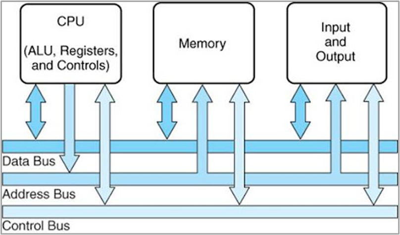
In computer architecture, buses are categorized based on their roles and functionalities. The three main types of bus in computer systems are:
Data Bus
- Purpose: The data bus is responsible for transferring actual data between the CPU, memory, and input/output (I/O) devices.
- Direction: Bidirectional (data can flow to and from the CPU).
- Key Features:
- The width of the data bus (e.g., 8-bit, 16-bit, 32-bit, 64-bit) determines how many bits of data can be transferred simultaneously.
- Wider data buses allow faster data transfers.
- Example: When the CPU reads data from memory, it uses the data bus to fetch the required information.
Address Bus
- Purpose: The address bus carries the memory or device address that the CPU needs to access during read or write operations.
- Direction: Unidirectional (information flows from the CPU to memory or peripherals).
- Key Features:
- The number of address lines in the address bus determines the maximum addressable memory.
- For example:
- A 16-bit address bus can address 2^16 = 65,536 memory locations (64 KB).
- A 32-bit address bus can address 2^32 = 4,294,967,296 memory locations (4 GB).
- Example: When the CPU wants to write data to memory location 0x2000, the address bus carries the address 0x2000.
Control Bus
- Purpose: The control bus manages and coordinates the communication between the CPU and other components by sending control signals.
- Direction: Bidirectional (control signals can flow both to and from the CPU).
- Key Features:
- The control bus carries signals like:
- Read/Write: Indicates whether data is being read or written.
- Interrupt: Notifies the CPU of external events requiring immediate attention.
- Clock Signal: Synchronizes operations across components.
- Status Signals: Indicate the readiness of memory or peripherals.
- The control bus carries signals like:
- Example: During a read operation, the control bus sends a “read” signal to memory, and the memory sends back a “ready” signal when data is available
| Bus Type | Purpose | Direction | Examples of Usage |
| Data Bus | Transfers actual data. | Bidirectional | Sending instructions to the CPU or data to/from memory. |
| Address Bus | Specifies memory or device locations. | Unidirectional | Pointing to memory address 0x2000 for a data operation. |
| Control Bus | Manages control signals. | Bidirectional | Sending “read” or “write” commands, handling interrupts. |
Bus Width
The bus width refers to how many bits of data the bus can transfer simultaneously. For example:
- A 32-bit bus can transfer 32 bits of data in one operation.
- A 64-bit bus can transfer 64 bits, making it faster and more capable of handling large amounts of data.
How Does the Bus Work?
Here’s a step-by-step explanation of how a bus operates during a typical task:
- CPU Request:
- The CPU decides it needs to access data or an instruction from memory.
- It sends the memory address where the data is stored over the address bus.
- Control Signal:
- The CPU uses the control bus to send a signal (e.g., “read” or “write”) to the memory or other devices.
- Data Transfer:
- The requested data is sent back to the CPU via the data bus.
- If the CPU is sending data to memory, the data bus carries the information in the opposite direction.
- Peripheral Communication:
- If the operation involves a peripheral (e.g., printing a document), the data is sent through the expansion bus to the appropriate device.
Elements of Computer Buses
A bus is a communication system in a computer that transfers data between components. To understand buses in detail, it’s important to know their fundamental elements. These elements define how the bus operates and ensure efficient communication. Here are the key elements of computer busses:
- Data Bus – Transfers data between components.
- Address Bus – Carries the memory or device addresses.
- Control Bus – Sends control signals to coordinate operations.
- Clock Signals – Synchronize data transfer timing.
- Arbitration Mechanism – Determines which device uses the bus when multiple devices request access.
- Protocols – Define communication rules for the bus.
- Bus Interface – Connects devices to the bus and translates signals.
- Termination – Prevents signal reflection for accurate data transfer.
- Power Lines – Provide power to connected devices.
- Buffers – Temporarily store data to manage speed differences between devices.
- Multiplexers/Demultiplexers – Combine or separate signals for efficient use of bus lines.
- Handshaking Signals – Ensure successful data transfer through acknowledgment.
Bus Interconnection Scheme in Computer
In a computer, buses are interconnected to enable seamless communication between various components. These interconnections are crucial for ensuring data, commands, and control signals flow efficiently. Let’s break down how buses interact:
Layers of Bus Interconnections
Buses in a system are often organized hierarchically or in layers to manage communication effectively:
A. Front-Side Bus (FSB)
- The FSB connects the CPU to the main memory (RAM).
- It’s responsible for handling data transfer between the processor and memory, which is critical for performance.
- Example: In older systems, the FSB was a bottleneck because all data had to pass through it.
B. Back-Side Bus (BSB)
- The BSB connects the CPU to the cache memory (usually L2 or L3).
- This connection is faster than the FSB, ensuring the processor has quick access to frequently used data.
C. System Bus
- Acts as the central communication highway, interconnecting the CPU, memory, and input/output (I/O) devices.
- Includes three components:
- Data Bus: Carries data.
- Address Bus: Identifies where the data should go.
- Control Bus: Manages the flow of data and instructions.
Types of Connections
- Shared Bus: Multiple devices share the same communication line.
- Advantage: Simpler design.
- Disadvantage: Bandwidth is divided among devices.
- Point-to-Point Bus: Direct communication between two devices.
- Advantage: No sharing of bandwidth.
- Disadvantage: Requires more physical connections.
Bridging Different Buses
To connect various types of buses, bridges are used. These bridges adapt the communication between different bus standards or speeds.
A. Northbridge
- Connects the CPU to high-speed devices like RAM and graphics cards (via the PCIe bus).
- Acts as a link between the FSB and high-performance components.
B. Southbridge
- Manages communication with slower devices like hard drives, USB ports, and network controllers.
- Bridges the system bus to buses like SATA, USB, and PCI.
Bus Arbitration
- Determines which device gets access to the bus when multiple devices request it simultaneously.
- Methods of arbitration include:
- Centralized Arbitration: A controller decides access.
- Decentralized Arbitration: Devices negotiate among themselves.
Bus Hierarchy and Communication
- High-Speed Buses:
Examples: PCIe and FSB. These handle critical, time-sensitive data like graphics processing and memory access. - Low-Speed Buses:
Examples: USB and I2C. These connect peripherals like keyboards, mice, and sensors.
High-speed buses often connect to low-speed buses through controllers or hubs.
Parallel vs. Serial Bus Interconnections
- Parallel Bus: Older systems relied on parallel buses (e.g., PCI) for faster data transfer but suffered from signal degradation over long distances.
- Serial Bus: Modern systems use serial buses like PCIe and USB, which offer faster speeds and reduced interference by transmitting data sequentially over fewer wires.
Advanced Interconnection Technologies
- Infinity Fabric: AMD uses this technology to connect CPU cores, memory, and GPUs in its processors.
- Intel QuickPath Interconnect (QPI): Enables faster communication between CPUs in multi-processor systems.
- HyperTransport: Used in some AMD systems for high-speed data transfer between the CPU and other components.
Examples of Interconnection Schemes
- Single Bus Structure
- A single bus connects all components.
- Pros: Simple and cost-effective for small systems.
- Cons: Becomes a bottleneck in large systems.
- Multiple Bus Structure
- Multiple buses handle different types of communication.
- Example: A system might have a high-speed system bus for the CPU and RAM and a separate I/O bus for peripherals.
- Pros: Better performance and scalability.
- Cons: More complex and costly.
- Star Interconnection
- Each device connects to a central controller or hub.
- Common in network systems but can be used for buses.
- Daisy Chain Interconnection
- Devices are connected in a chain, one after the other.
- Pros: Reduces physical connections.
- Cons: Failure in one device can disrupt the chain.
Bus Architecture
The design and organization of buses in a computer are referred to as bus architecture. Common types include:
- Single Bus Architecture:
- All components share a single bus.
- Advantages: Simple design, low cost.
- Disadvantages: Slower performance due to bus contention (multiple devices sharing the same bus).
- Multiple Bus Architecture:
- Uses separate buses for different functions (e.g., system bus, I/O bus).
- Advantages: Reduces bus contention, improves performance.
- Disadvantages: More complex and expensive.
- Hierarchical Bus Architecture:
- Organizes buses in a hierarchy, with faster buses at the top (e.g., system bus) and slower buses below (e.g., expansion bus).
- Advantages: Balances speed and cost.
- Disadvantages: Increased complexity.
- Serial Bus Architecture:
- Data is transmitted one bit at a time over a single line (e.g., USB, SATA).
- Advantages: Simplifies physical connections, supports longer distances.
- Disadvantages: Slower for short distances compared to parallel buses.
- Parallel Bus Architecture:
- Transmits multiple bits simultaneously over multiple lines.
- Advantages: Faster for short distances.
- Disadvantages: Signal degradation over long distances.
Examples of Bus Standards
Modern computers use a variety of bus standards for different purposes:
- System Bus:
- Connects the CPU, memory, and motherboard.
- Example: Front-Side Bus (FSB).
- Expansion Bus:
- Connects external devices and peripherals.
- Examples: PCI (Peripheral Component Interconnect), USB (Universal Serial Bus).
- Memory Bus:
- Connects the CPU to memory modules.
- Example: DDR (Double Data Rate) buses used in RAM.
- Storage Bus:
- Connects the CPU to storage devices.
- Examples: SATA (Serial ATA), NVMe (Non-Volatile Memory Express).
Two Sides of a Bus
Think of a bus like a road that allows different devices in a computer to communicate with each other. There are two important parts to a bus:
1. Logical Bus (The “Rules” of Communication)
- The logical bus refers to how the data moves and how the devices talk to each other. It’s like a set of rules or a protocol that governs the flow of information.
- Just like a language, the logical bus ensures that the data is transferred correctly and in the right order.
Example:
In networking, Ethernet is an example of a logical bus. It allows multiple devices (like computers, printers, etc.) to communicate with each other over a shared medium (like cables or Wi-Fi). All the devices follow the same set of rules to send and receive data.
2. Physical Bus (The “Hardware” of Communication)
- The physical bus is the actual hardware that connects the devices, like wires, circuits, or tracks on a motherboard.
- This is where the data travels. It’s the “road” where the signals (data) move between devices, just like how cars travel on a physical road.
Example:
The physical bus could be the actual copper wires inside a computer that connect the CPU, memory, and other devices, allowing them to send signals to one another.
Benefits of a Bus System
- Efficient Data Flow:
- Ensures smooth communication between components, allowing the computer to perform tasks seamlessly.
- Scalability:
- Makes it easy to add new hardware components (like a new hard drive or graphics card).
- Cost-Effective:
- By sharing a single communication pathway, buses reduce the need for complex wiring and connections.
- Standardization:
- Common bus standards (like USB) make devices compatible with various systems.
Common Issues with Buses
- Bus Contention:
- Occurs when multiple devices try to use the same bus simultaneously, causing delays.
- Bandwidth Limitation:
- The speed and width of a bus determine how much data it can handle. A narrow or slow bus may create a bottleneck.
- Overhead:
- As more devices are connected to a single bus, managing communication becomes more complex.
Summary of What is Bus in Computer
A bus interconnection scheme facilitates communication between a computer’s components, such as the CPU, memory, and peripherals. It includes high-speed and low-speed buses connected via bridges like Northbridge and Southbridge. Shared or point-to-point connections, arbitration mechanisms, and serial or parallel data transfers ensure efficient operations. Modern technologies like Intel QPI and Infinity Fabric enhance speed and scalability, making the system optimized for performance and reliability.